
Fig.1. Varieties of spring arrangement in a mass-and-spring model.
Electronics and Communications in Japan Part 3: Fundamental Electronic Science, pp.1919-1926, 1998.1
Shinya MIYAZAKI, Takami YASUDA, Shigeki YOKOI, and Junichiro TORIWAKI
A new technology has been used to construct virtual environments in the computer, where objects behave as if they were real ones, has been drawing attention. This paper studies virtual manipulation of elastic objects as a fundamental example of nonrigid materials. An elastic object modeled by a combination of material points and springs can be deformed with a rigid cylindrical manipulator controlled by a mouse in imitation of actual actions such as hitting or thrusting. The dynamic response of the elastic object in a collision with the manipulator is generated by a numerical method of solution based on physics and is displayed in real time. An improved spring model is presented in which the amplitude is restricted by elastic energy when the elastic object receives extensive external force. The results of implementation show the effectiveness of the spring model and interactivity of the system.
Key words: Virtual reality; computer graphics; space manipulation; elastic object; spring model.
1. Introduction
With the rapid progress of computation and graphics ability, a new possibilities in human-machine communication taking advantage of computer graphics are attracting great interest. High-performance processor units and graphics engines have realized interactive simulation dealing with high-quality computer graphics images that demand instant computation of motion and expensive rendering, such as shading or texture mapping in real time. Many kinds of virtual reality (VR) systems allowing human-like interaction with objects defined in the computer have appeared [1]. Development of interface devices such as 3D position sensors and stereo imaging systems has become a center of study [2-6]. On the other hand, methods of modeling that implement various kinds of properties of real objects and allow one to interact with them have not been attempted because they are usually realized by software and are expensive in terms of processing time. Therefore, the properties have been limited to simple ones such as rigid objects in these systems, as advantageous for real-time simulation. Employment of nonrigid objects, however, is indispensable if VR applications are to reach a practical level.
In this paper, we describe a virtual manipulation system for elastic objects as a fundamental example of nonrigid materials, in which objects can be directly deformed with a rigid cylindrical manipulator controlled by a mouse, simulating actual actions such as hitting or thrusting. Combinations of material points and springs represent internal elasticity of deformable objects and the surface elasticity of rigid objects. A numerical method of solution unifies their dynamic behavior based on physics, and the result is displayed as computer graphics in real time.
In the field of CG animation, it is a usual to model a deformable object in a finite number of elements on the basis of its local property. A mass-and-spring lattice represents an elastic object, which is effective if the variety of generated motion is limited and computation time is available. However, when it is applied to interactive simulation, pronounced divergence of elastic oscillation appears in some springs and triggers destruction of lattice. It is often difficult in interactive simulation to avoid divergence because motion is made indefinite by interaction and must be processed in real time. Divergence especially appears in strong collisions caused by interactions such as pushing or thrusting in which the velocity difference between an object and a manipulator is large. It is an important matter how to avoid divergence in implementation of interactive systems. We propose an improved spring model to cope with the problem of divergence. If some springs have excessive energy owing to the collision force locally applied to the object, it is distributed over the whole body and the lattice keeps its structure.
2. Framework of Manipulation
Many more kinds of manipulation can be considered for elastic objects than for rigid ones: hitting, pushing, bending, twisting, stretching, cutting, tearing, and so on. We develop here the simplest one, pushing, which is also called hitting or thrusting when motion is comparatively fast, because it can be realized with only a rigid manipulator. The structure of objects is unchangeable in such interactions while cutting and tearing divide an object into two pieces. Another framework is to base modeling on physics in the development of virtual environments, namely, interactions between objects and the manipulator. Within these frameworks, the following items should be defined:
(1) shape of manipulator and interaction;
(2) model of elastic objects and motion generation;
(3) model of collision between elastic objects and a manipulator;
(4) environment including elastic objects and manipulator.
We here restrict item (4) to a simple case for real-time simulation, in which only one elastic object and only one manipulator are included in a cubic room. The other factors are defined in the following sections.

Fig.1. Varieties of spring arrangement in a mass-and-spring model.
2.2.2 The kind of force
Elastic forces and damping forces act on material points as internal force and gravity acts as an external force when an elastic object moves in a gravity field without collision processes. Equation (1) specifies the vector of force Fi operating on the point i . with mass of points mi , gravity constants g, elastic constant kij , natural length of springs Lij , and damping constant of springs Dij . And the spring between the point i and the point j has elastic constant kij , natural length of springs Lij , and damper Dij . pij and vij are the relative position and relative velocity of the point i with respect to any point j which is connected to point i:
 (1)
(1)
Repulsion and friction additionally operate on both elastic objects and the manipulator in a collision. They are discussed in section 2.3.
2.2.3 Numerical methods of solution for dynamics
Analytical methods are not suitable to solve dynamic equations because they must take account of various situations caused by interaction. The only practical method is the numerical one. We employed Euler's method, which is fundamental in numerical analysis. The velocity Vi(T) and position Pi(T) of the point i at discrete time T are sequentially specified as.
 (2)
(2)
 (3)
(3)
Here, Fi(T) means the force operating on point i at time T. DT is the time step of evolution. Velocities and positions of points are renewed step by step in time. If DT is sufficiently small compared to the cycle of spring oscillation, the simulation is considered to be reliable enough.
2.3.1 Elastic layer on the surface of rigid objects
The intensity of rebound between an elastic object and a rigid object should be due to the properties of both. We assume a thin elastic layer on the surface of the rigid object to represent some elasticity. For material points penetrating into the elastic layer, a repulsion force is generated according to the depth of penetration. It is simply implemented by putting springs between each of the penetrating points and the basis of the elastic layer (Fig.2). If the natural length of those springs is equal to thickness of the elastic layer, the repulsion force becomes the same as described in Ref. 13. The elastic constant of the springs in the elastic layer controls the hardness of the surface of the rigid object. Friction is determined according to the repulsion force, which is proportional to it.

Fig.2. A simulated elastic layer on the surface of a rigid object.
2.3.2 Reaction to manipulator
A manipulator receives a reaction force that is equal to the total of repulsion and friction operating on the material points in elastic objects. If the reaction force is not represented in any way, the interaction will be unnatural one. It is reflected in the movement of the manipulator, which appears to be repelled when the reaction force operates.
3. Improvement of Elastic Object Model
Numerical methods sometimes result in unsatisfactory accuracy or occasionally go to divergence when the approximation is inappropriate. Discretization of a homogeneous elastic body by the mass-and-spring model is certainly effective for interactive simulation in real time. However, springs without a proportionality limit are not proper for the case in which elastic objects are greatly compressed or stretched, because they permit infinite increments in their amplitude. In this section, constraining the amplitude of the springs on the basis of the elastic energy, an inelastic factor is included in the spring model. It works well to suppress divergence of oscillation.
We can consider another reason for divergence, the delay in propagation of force in a body. Force applied to the surface of an object is propagated into its body with delay which depends on the discrete time resolution DT , while it is instantaneous in the real world. If the number of springs linking two points is i, the delay between them is i DT. This type of divergence grows with DT and the size of the lattice.

Fig.3. Exchange of material points in a lattice.

Fig.4. Three kinds of models having rigidity and elasticity.
 (4)
(4)
Here, v1, v2, and l mean the current velocities of both end points and the length of the spring, respectively. The first and second terms on the left side indicate the kinetic energy depending on the magnitude of the relative velocity | v2 - v1 | and potential energy depending on the displacement | l - L |, respectively. The term on the right side is the potential energy at the moment when the spring is completely compressed (or stretched). The following relation is derived from inequality (4):
 (5)
(5)
The ratio of elasticity and rigidity that minimizes rigidity is determined according to inequality (5); | v2 - v1 | must be less than a threshold q which depends on the current length of the spring l .
 (6)
(6)
Increasing and decreasing the velocities of both end points by Dv respectively, the relative velocity between them is reduced to an acceptable one.
For implementation, a new procedure called distribution of velocities is added between the ordinary procedures of renewal of velocities and renewal of positions that correspond to equations (2) and (3), respectively. The procedures are as follows:
(a) Velocities are ordinarily renewed according to equation (2), in which springs are completely elastic. (b) Velocities of end points are increased or decreased by Dv in equation (6) to reduced the relative velocity between them in springs which do not satisfy inequality (5). (c) Procedure (b) is repeated until every spring satisfies inequality (5). (d) Positions are ordinarily renewed according to equation (3).
Procedures (b) and (c) correspond to the distribution of velocities procedure. These procedures do not influence interactivity greatly because they are applied only to a part of the springs. They also provide the effect of reducing the delay in force propagation noted in section 3.1.
Figures 5 and 6 show the effect of the fusion model in rebound motion. They are fundamental examples of four springs connected in series and three springs constructing a triangle element. In Figs.5 (b) and 6 (b), the vertices keep their relative positions, while they exchange in Figs.5 (a) and 6 (a).

Fig.5. Collision of four springs connected in series.

Fig.6. Collision of three springs in a triangle arrangement.
4. Setting up Parameters for Real-Time Processing
Interactivity is an important factor in implementation of the system. The conditions on parameters for real-time processing are indicated and the values are experimentally derived.
n Tc + Tr < Ti (7)
DT = Ti / n (8)
Here, Tc and Tr are the processing times for computation and rendering, respectively. It is also important to select the most suitable interval for Ti so as to minimize waste of time if there are more than one candidate.

Fig.7. Distribution of process time within an update interval.
 (9)
(9)
 (10)
(10)
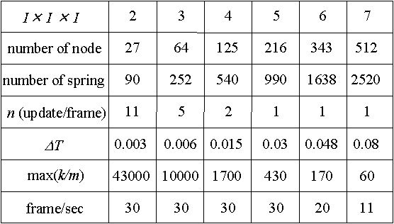
Real-time processing is realized for 5 X 5 X 5 with 30 frames per second rendering. If 10 frames per second is acceptable, it is expanded to 7 X 7 X 7.
5. Contrast of Parameters between Models and Real Objects
It is also important to contrast parameters of models with those of real objects. Here, we try to define the spring constant of the model with Young's modulus that gives a fundamental elastic property of real objects.
Young's modulus defines the stress per unit area that is associated with a strain per unit length. When an external force operates perpendicular to the face of a cube, it is mostly the springs parallel to the direction of the external force that operate. Ignoring the contribution of the other springs, Young's modulus E [ dyn / cm2 ] corresponds to the spring constant k [ dyn / cm ] divided by the length L [ cm ] of edges of the cube:
E = k / L (11)
Another parameter the density d [ g / cm3 ], must be given. It corresponds to the mass of points m divided by the cube of the length L, given a sufficiently large number of cubic elements:
d = m / L3 (12)
By controlling parameters m, L, and k according to equations (11) and (12), the models are adjusted for an elastic object with arbitrary Young's modulus. However, parameter L is given the lower limit derived from the upper limit of k / m indicated in section 4:
 (13)
(13)
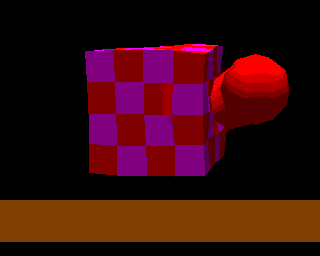
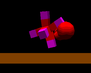
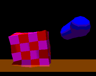
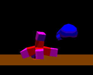
According to inequality (13), for instance, to realize rubber with a density of about 1 g / cm3 and a Young's modulus of about 106 dyn / cm2 by using 5 X 5 X 5 elements, the edges of the cubic elements must be more than 50 cm. This is unreasonably large compared to the things we usually deal with. Therefore, real-time processing is at present available only for soft objects whose Young's modulus is far smaller than that of rubber. However, it will be realized for models which correspond to rubber in the near future because computers are advancing rapidly and mass-and-spring models can be processed in parallel. Figure 8 shows elastic objects constructed of several cubic elements interacting with a manipulator and rebounding from the floor.
 |  |
 |  |
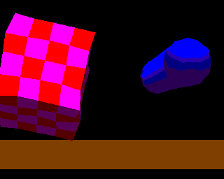 | 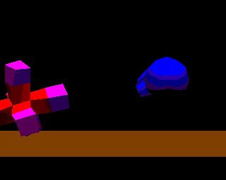 |
Fig.8. Rebound of an elastic object from a manipulator and a floor.
6. Conclusions
In this paper, we have studied virtual manipulation of elastic objects represented by mass-and-spring models, though the number of elements is limited for real-time processing. A spring model was introduced which has properties intermediate between rigidity and linear elasticity, realizing limited deformation in an intense collision. The system can be usefully extended to practical applications that deal with nonrigid objects in the fields of education, sports, medicine, and so on. Though the objects were limited in shape to a set of cubes, direct free-form arrangement of springs will be developed in the next stage.
Acknowledgments. The authors would like to thank professor Teruo Fukumura of Chukyo University and their colleagues in Toriwaki Laboratory of Nagoya University for their encouragement and useful advice. This research was supported in part by the Grant-in-Aid for Encouragement of Young Scientists and by the Advanced Software Enrichment (IPA) program.